DPFuzzer: A Platform Independent DisplayPort Fuzzer by Simon Vincent And Ross Cuthbertson
Show transcript [en]
hello everyone and welcome to our talk um this will cover some of our recent vulnerability research we've been doing on displayport my name's simon and this is ross so today um what our aim is is to try and cover the process um that we followed when we were building our platform independent clayport fuzzer um this puzzle was quite successful found quite a number of bugs so hopefully it'll be interesting so we're going to kick off with a little introduction of who we are then we'll go through some technical background of what displayport is how the protocol works and what it's used for and then we'll go into details of um how we built the fuzzer how it works
um and what it can do we'll then try and do a live demo um before covering a few details of some of the bugs we found and then hopefully have some time some questions so we are the uh cyber research group rayfin uk we're a fairly small team and we do fairly niche security services and we provide these to the mod as well as other government departments and some internal raping teams we've been doing cyber research at raytheon for about seven or eight years now however in 2019 we formed a new team under our strategic research group and in this we focus on a few areas such as vulnerability research product characterization and digital forensics
most of our researchers work on a mixture of customer projects as well as their own research and this is funded by raytheon and this talk is an example of that so all this displayport research was funded by raytheon and it's no connection to any of our customers and if you find this interesting and you know you've you want to work with us or work for us we're currently hiring so please visit our website or drop us an email [Music] hi good afternoon so i'm just going to introduce some fuzzing terms just briefly so a simple fuzzer sends some random data known as a test case to a program to see if it crashes basically it's typically more effective to
randomly mutate some valid data or input corpus and this is the approach that we will be using as we can apply this kind of testing to many types of devices and we'll look through this sort of flow diagram many thousands of times during the fuzzing campaign and in this presentation we're going to describe how we achieved each step so i displayport it's a popular interface uh it's quite ubiquitous now it's supported over usbc contains a bi-directional auxiliary channel which the displayport uses to negotiate video transmission of the display and critically these messages on this channel are processed by the graphics driver which is typically typically operated at a privileged level so there's some potential for some
interesting bugs so there's a lot of research in hdmi it's not a great amount in well there's no research that we found on displayport um public research so as well as present providing some research on displayport our presentation uh i'll go a bit more in depth on how to create the hardware required to target many of these types of devices i guess the other takeaway from this slide is these sort of bugs have been around for about a decade so i guess it's lessons learned hasn't really happened so what is displayport it's a digital display interface it connects a computer or a source to a display or a sync so i head over to wikipedia
it tells me that it carries video audio and data over channels and then there's a reference to other data uh and points to the the displayport specification which we'll have a look at next and the specification states that there are three main channels there's a main link which is the high speed video link which carries video from in one direction only from the computer to the display there's a hot plug detect which is basically a pin uh which when driven high or voltage is applied it'll wake up the computer and there's the auxiliary channel which is a bi-directional communication channel and this is what we're going to target so what is the auxiliary channel for
well this sequence diagram contains some of the messages found on the auxiliary channel when you connect to the display hot plug detect triggers a software interrupt the graphics driver will make a read request and the display will respond with some data which is passed by the graphics driver and this data includes edid or display capability information such as resolutions etc and when setup was complete video transmission starts there are many more protocols which are supported by dp the displayport edid which i mentioned but there's others which support encryption topology discovery um encryption uh i said and some other messaging systems and some of these are quite complex so our aim is to create a platform
independent uh displayport fuzzer and we want to target many devices and this means we need to know how to transmit and receive messages on the auxiliary channel so we have to understand the displayport specification from the physical layer up at the physical layer we need to understand the characteristics of a differential signal or lvds at the top we've got a typical signal from a microcontroller and at the bottom we have a differential signal which is used to carry the auxiliary channel messages and basically voltage voltage polarity is used to represent bits on the line rather than voltage amplitude and differential signal is used as it supports high data rates and it copes well as noise
so we need some electronics to convert between the single and differential signals and this is called a line driver and it's represented in this image by the triangles um so serial signals from your computer will be converted to differential signals as found on the actual cable itself and then that's converted back again on the display side the other thing uh to note on this slide is that the transmit and receive electronics share the same channel and this is called a half do duplex as only one side can transmit at a time which is why the auxiliary channel is a request response based messaging system so you can observe the differential signal by connecting an oscilloscope to the two pins on the
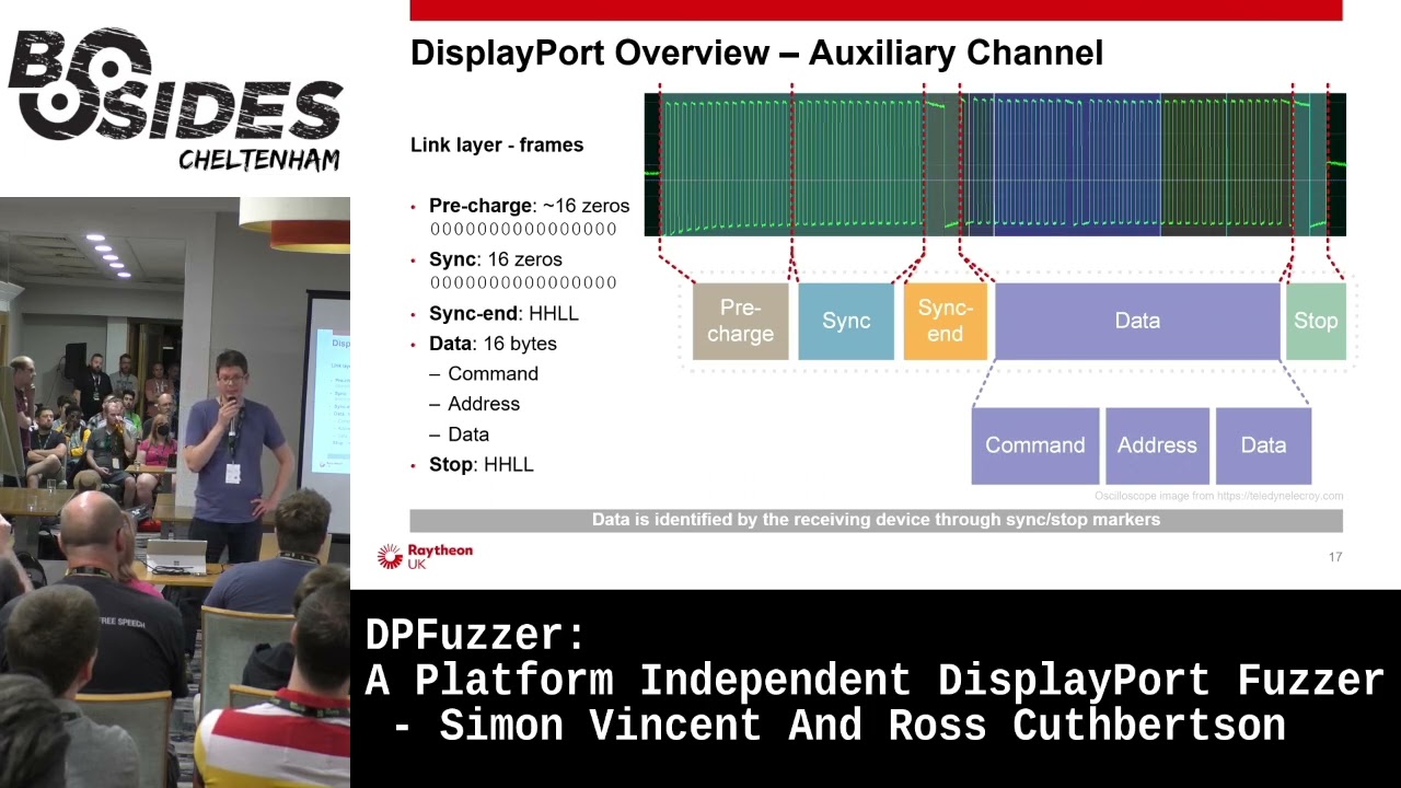
displayport connector the bottom image is the two traces from the top overlaid and you can clearly see the differential the characteristic differential signal here we can also see data so how is the data encoded data is encoded using manchester encoding which basically means data is xored with a clock signal and this is useful because it requires less spins on the connector it breaks up long periods of of high or low and this suits the electrical characteristics of the channel but it also means that we can distinguish between other markers and data which i'll talk about next at the link layer we need to understand how the data is framed so this helps the receiver identify when
the message is on the channel so the channel is idle to begin with and then it's at the start of the message is identified with zeros and then there are two markers so you got the first marker and the second marker and these identify the start and the end of the data so as mentioned earlier these markers don't conform to manchester encoding therefore the data section can be clearly identified and these sections help when implementing a state machine for example just to note that the data can be further divided into other things depending on what protocol is used um that's done in software
so the auxiliary channel is a request response based messaging system and they are framed in exactly the same way and this makes it easy for us to change our buzzer to mock a sync uh sync or source device so for example we can target multiple types of device um such as a display or a computer and as you can see there's a short period of time in between the request and response has a maximum of 300 microseconds but typically we want to be much shorter than that to keep timings out and this is a constraint that we need to deal with when designing our system so messages are handled at the application layer messages like edid as
i mentioned earlier and this simple example shows the display capabilities such as resolution are encoded in the data messages are typically processed in the graphics driver and so using the electronics described earlier we can promise currency observe messages on the on this channel between a computer and a display and these messages provide us with an input corpus for the fuzzer which leads to how we develop the fuzzer i'll hand you back to simon [Music] so what was our goal so our initial goal was to develop a fuzzer for a gpu driver so on the screen you can see there's a diagram and the gpu is the source device on the left and the fuzzer our fuzzer is
pretending to be a sync device on the right and we've got some data we've captured off a bus or from connecting a monitor to a gpu we've intercepted that captured valid data what we do is we mutate that data we then send a hot plug detect we send that hi so the gpu sensor request and essentially what we're trying to do is send a mutated response so a response which is invalid and then we detect see whether the target's crashed so what might this mutated response look like so the gpu might request four bytes and instead we might return a single byte but we might set the size field to 99 bytes and we'll see what happens
really so what what stages do we go through so at the very beginning we read the spec or or certainly little bits of it it's it's incredibly long um hundreds hundreds and hundreds of pages and also it's quite hard to get hold of the spec technically you have to pay but you can find it if you google um then once we've got that and we understood you know how we can interface with this specification this protocol we started building a hardware interface so we could read and write data on this channel once we could do that we then started building software to decode the protocol as well as be able to record the data we
see on there and then once we do that we essentially we've got something that we can get rid of a monitor we can plug our fuzzer directly into a gpu and we can mimic a monitor so we can just replay data that we've previously captured then we add in things like mutating of test cases so we start adding a bit more randomness and then build the photo up adding crash detection recording test cases and then if we get lucky and have some crashes we can then add functionality to replay those crashes and minimize them turn them into sort of proof of concepts so as ross said we've got a differential signal but it's much easier for us if we turn
that into a single ended signal because we can then use a micro processor quite easily um interfacing with that so one of the first things we did was we essentially we trawled through rs farnell looking for something that would meet those needs so we got an lvds interface chip that essentially we needed something that supported three volts um could do at least one megabits per second as the auxiliary channel can cope with that so we had to how to cope with that speed and we also wanted something that could both send and receive data so to be a driver and a receiver as well as all that we had to sort of comply with the displayport spec
so there was a useful diagram in the spec which you can see the bottom right you can possibly see it anyway and this this was very useful so it tells us exactly what what components we need to essentially interface with the bus so we have to use some pull-up pull-down resistors we have to do termination resistors and also some ac coupling capacitors there and this allows us to essentially be a monitor and drive that bus and the gpu will be able to detect that so this is sort of the circuit we we came up with to start um you can see all the discrete components there are connected to the displayport channel and that goes into our lvds chip and
then we've connected the output the lvds chip into a logic analyzer essentially so on the bottom you can sort of see essentially you can see the sync frames then you can see the end of sync flag some data and end of uh data marker and on the right it's just a little picture showing sort of our initial prototype pretty nasty um essentially we we took a knife to a displayport cable but it works and it's quick so now we've got this signal how do we digitalize it we need to get it into something so we can process it so essentially we we had two options that we could come up with one was use a microprocessor one was
using fpga we went down the microphone route because it's just much quicker to develop people have told us use fpgas but it would have taken ages um so in the end we set it on a tincey 4.1 board it's got an arm processor on it that runs at 600 meg it's got usb on there so we can get data in and out pretty quickly as well as that it's got some good hardware peripherals there so it's got dma timers and lots of useful things like that so we've got a microprocessor that runs at 600 meg but what we actually found was when we first implemented it we triggered it off interrupts and did all the processing in software this
could read fine but when we started trying to send data as well it just couldn't keep up and we were losing data so we had to get a bit creative and in the end we settled on a design which um offloaded a lot of this onto the harper peripherals of the tennessee board so we could actually chain a lot of the hardware peripherals up so we chained inshot controller timer and dma engine so the interrupt controller was configured to generate an interrupt every time the signal went high or low um this was then went into a timer so the timer is essentially measuring how high how long how many clock cycles the signal was high or how many was low and
feeding this into dma engine which would put it into a circular buffer for us so we end up with a circular buffer with lots of data in there and essentially then all we need to do is write a optimized c code state machine which could quickly go around that buffer looking for the sync patterns and when it sees the sync patterns it knows in between those sync patterns we've got valid data so we can then decode that using manchester encoding extract all the commands address and data and chuck it out the usb port and then this also works in reverse so if we want to send data we can receive data on usb port and do the opposite
so what do we interface this with essentially we wrote some python code on a pc and this was sort of the master of the fuzzer so it orchestrated everything it's communicated with the hardware interface board as well as generating us test cases so we recorded test cases um from a normal interaction over the over the wire and then we used an open source library called a ramanza and this would mutate so it would add random in us flip bits things like that and we could then take these test cases and we could feed them into a hardware interface board which would put them on on the displayport channel this fuzzer would also handle things um
like logging the test cases to disk which wouldn't have been very practical on an embedded device as well as doing crash detection so we did crash attached in the end via icmp so a target like a windows pc um essentially you can keep pinging it and then when it crashes it will stop responding to pings so you know you've had a crash or something has gone wrong somewhere so we we made several different modes um that we could support so the first thing we implemented was a sniffer mode so essentially this was the hardware interface board and the fuzzer would sit between a monitor and a gpu and we just capture data so we'd build
up a library of what sort of valid data we'd see across there and then this would then be used in our fuzzing runs we then moved into adding functionality to fuzzer source device so it was a driver gpu driver by using that test data and mutating it and then we had then added a feature to sync fuzzer a sync device so a monitor or display we started off by using very just completely random data um so we didn't respect the protocol at all so if we were asked for four bytes we might return 16 bytes or something like that but what we found was certain gpu drivers didn't really like that so they would detect
as soon as you send too much data they just throw everything away so you wouldn't get very far into the driver or find any interesting bugs so we we added a new mode which we sort of termed a goodish mode which would respect the basic protocol so if we ask for four bytes we'd return four bytes and we'd do things like acts properly but the data inside that protocol was mutated and essentially invalid and what we found was um if we started fuzzing um in normal mode for a day or two um and we hadn't found anything we'd switch then into goodish mode and leave that for for a week or two and that sort
of was quite effective that approach so what did the architecture look like so in the top left we've got our pc running some python code and then in the top right we've got the gpu in a desktop pc the fuzz is doing crash detection by pinging it but also it's also controlling the power to the pc so what we found was in certain cases the pc would crash so badly that it wouldn't reboot it wouldn't be responsive at all so essentially we had to add something to automate power cycling it this python fuzzer would then talk via usb to our hardware interface board um on our tenancy board which would then interface directly into the displayport cable so
we can inject data in and receive data via our lvds transceiver and discrete components so what did hardware look like we started off with a fairly rapid prototype i suppose um lots of cables um and sort of loose connections which worked worked pretty well this lasted a few months before um essentially we found it was a little bit unreliable when you're working from home and you've got toddlers and cats they like to pull out cables which isn't ideal when you're fuzzing for a couple of weeks um so we then moved to developing a proper pcb which looks better and it's a bit more reliable and essentially on that we've got two ports for connecting either a gpu or a
monitor and some jumpers there to configure what what you what you're fuzzing so what does a basic fuzzing run look like this is when we're fuzzing a gpu we start up in in the top um and our python python code at the top is generating some test cases for us from the ones that we've recorded we then will send a number of these to our hardware interface boards the tinsey would buffer up maybe 500 samples the tenancy would then toggle the hot pin hot plug pin um which would kick the the gpu off so the gpu would then go oh i've got a monitor attached it send a request and we would receive that request in the tensi decode
it and then we'd select an appropriate test case um to respond with send this to the gpu and then the gpu you know we'd go around this loop multi multiple times essentially until either the target crashed or we ran out of test cases so this bottom loop on the left will just keep going around around there millions and millions of times
right let's try try demo so i've got my python code on this machine and then we've got our hardware interface board connected by usb to this laptop [Music]
[Music] get it
so essentially um this is just a command that's just telling our fuzzer to replay some test cases so we've got some test cases that we've built to proof of concept and we're going to send this to our teensy board which is on com8 and then the tennessee board is receiving it and it's now going to start replaying test cases so gpu will be sending requests and we'll be responding with hopefully bad data and if any luck it'll crash hey [Applause]
[Music] cool so we've got a crash um what do we do now so we've got blue screen of deaths the first thing we did was see if we could reproduce it so essentially when our father detects a pc crashed it logs all the test cases we've got so this might be you know a million test cases we sent it to crash so it logs that um and it would replay them and if it crashed again then it goes great i've got something that's you know nice and reliable and reproducible the next step would be to collect a crash dump so pcs like windows mac um when you get a crash like that they'll write a log file
to the disk and you can configure them to write a small one large one whatever so we'd pull that off load up in a debugger and we could see exactly where it was crashing what function was causing it what driver it was and essentially from that we could see where we created we found a another unique crash or whether it's just one we've seen before we then take our say 1 million test case test cases um and we try and minimize that so essentially we we keep removing test cases and replaying it over and over again until we've got right down to the minimum amount of data we could send to cause the crash so we might get this down to
from sending a million requests and responses down to like 20 or something like that
once we've got these smaller test cases we then look to decode them into human readable actions so in the top right you can see an example of the data it's not a zero day don't worry so you've got eight zero zero zero six and essentially you wrote a python script which scanned and parsed the displayport specifications it scrapes data from all the registers um and you could then take in data like that and decode it into human readable form so we can see that that maps to a request message that's doing a displayport native right to address hex 600 and it's sending is writing one byte which is zero one we're then responding with an ack
um but we're you know just adding some f's for fun so we're sending six bytes back as well and this goes on and on essentially once you've got a few test cases there and and things like this decode in human readable form you can then analyze them look for patterns and then develop a proof of concept and then the next stage is essentially um you can disclose it to vendors and with any luck they fix the bugs now hand back to ross talk about some of the bugs yeah so the fuzzer is a success through a lot of hard work we've got some bugs i guess more importantly the vendors are releasing some driver updates
but unfortunately we can't go into any uh details as we're still going through uh coordinated vulnerability disclosure but we can't talk about the types of bugs that we found it's worth noting that no privileges are required this type of attack as you've seen the demo pc screen was locked um crashes with triage as simon mentioned and we discovered a number of issues as you can see some of them more interesting like out of one rights um yeah and we we also target some sync devices such as a display and found issues there sort of highlights that software issues are present in many types of devices just to reiterate that the physical access is required mitigation is quite difficult
because we've just violated our first rule yeah so just to summarize quickly then uh we identified a high-risk target which had no public research um researched how displayport works we use this to prototype some hardware to read and write auxiliary channel messages and then use that to create a platform independent fuzzer which discovered lots of bugs and started some coordinated vulnerability disclosure well there's more research that we can do there's areas we can optimize the fuzzer we could test more devices charge more issues and of course continue to work with the vendors to to fix these issues thank you very much any questions [Music] [Applause] [Music] yeah any questions stunned silence yep are we going to open source it uh
unfortunately we can't because we're still going through a vulnerability disclosure um so yeah uh obviously we've got this material but uh yeah we can't disclose that just yet
yeah so we monitored uh the target if it crashed using ping um a simple case [Music] oh sorry for a monitor yeah
[Music] so from sort of coming up with the idea i suppose until developing and finding the first crash took quite a while because we weren't working on it full-time it was sort of just in between projects um it's kind of a lockdown project i suppose so it's been on and off i suppose for a while um probably a couple of months i'd say to find the first bug and then it was just i mean it was quite quick and easy to get a device to crash the difficult bit was then turning that into something that's reproducible and consistent and sort of detecting that target crashed and capturing the test cases that took quite a bit more work
but getting just a pc to crash was quite easy really
probably not just like there's quite a lot more than we expected
i don't really know um i think most of them looked like they were in the drivers but sometimes we were seeing weird things with gpus as well so sometimes gpus would just hang and the fans and then would just go crazy so not we don't have no idea what's going on there but down to the vendors to try and work out
cool i think that's it
Related talks
 26:02
26:02 9:40:42
 25:39
25:39 33:56
33:56 48:57
48:57 48:31
48:31