A Look At Internet Of Things (IoT) Hardware Hacking
Show transcript [en]
for coming to my talk. Uh, IoT hardware hacking. So, a quick little history about me. I've been at Rapid 7 for a little over 11 years. I do a lot of research over the years. We got it listed over there. I can be reached at to my name, email address or uh onx uh if you want to reach out to me. I use that specifically for research type stuff. Uh I've been doing uh IT IT security for 25 30 years something like that and been doing research for over eight years now specifically for rapid 7. So that's enough about me. So let's get going. So I want to I want to create a kind of a creative dive into IoT
hardware hacking. There's a number of data out there, YouTube videos on all the basics, but what I'm going to do is we're going to break this up into a number of just short pieces where we touch on various ideas to get you start thinking about how to interact with hardware, how to engage it, do various attacks, maybe how to pull firmware off devices that are problematic. And kind of at the end, we're going to talk about rooting a camera. So, I have a video of rooting a camera and we're going to kind of walk through that. This particular camera uh is one that we're going to use for uh IoT hardware hacking exercises at Defcon. So, you get to see the what the
exercise is basically going to look like. So, if you show up out at Defcon, by all means, swing by the IoT village, check out what we're doing. We'll have uh I'll be there. We'll be setting up multiple machines. We'll also have Rapid 7's pin test team, their IoT pin testers help running the whole thing. And it's just fun interaction on hardware hacking. So, let's go ahead and get started. The first thing is is I want you to give you a thought around IoT system testing methodologies. Um, the first thing I think of this is I think about what we I call the three keys of the kingdom. When we're focusing on hardware, there's three things I want to do with that
hardware. I want to get the firmware off of it. I want to look at interchip communications and I want to get root access with those type of things. I'll be able to do some pretty cool stuff. You can't always get all of these. Sometimes you just can't get the firmware off of it. There's been times we can't get root access. And in cases of those complex devices, I started doing research in interchip communication analysis where we tap into the communication between microprocessors on the device where we can get a big vision of the overall end toend security because things flowing between microprocessors is rarely ever encrypted. So now we can get access to really interesting stuff. But in general
on a high level, a number of years ago when I took this job, I really didn't know what IoT was. The definition of IoT is still kind of vague and confusing. So I started thinking about it and I started thinking about it from a tester's perspective. When we're going to test IoT, do we want to get overly focused on just the hardware? Because that's not IoT. That's the small piece of IoT. IoT is made up of three core pieces. It's going to be made up of the embedded device, but then it's going to have some kind of management and control functionalities. It could be web- based, could be on the internet, it could be an
interface on the device. Uh it could be a mobile app, it could be a thick client, it can fall into a number of different realms. And then you also have cloud service, cloud APIs and those kind of functionalities. So IoT cannot function on its own. It has to function within this environment. So when you start thinking about security, don't just focus on the hardware. Think about these other pieces because any security failures in any one of these pieces can lead to further security failures in the other pieces. And by analyzing the security not just at the individual component level, but also at the communication interaction between these various devices can lead to a lot of
cool access data and vulnerabilities in IoT. So, I want to get into interacting with hardware. The this first one here is kind of an overlay method. So, you get a device, you want to figure out where I'm going to tap into this device, and sometimes it gets confusing. There's not a header on there marked, hey, I'm UART. Hey, I'm JTAG. You may get a device that has nothing marked on it at all. You have no idea what you're actually looking at. So we started a process in thinking about this is an overlay method where we take reversed images of the device and we overlay [Music] them. So now we see the other side. So we take a 50% pass through on this and
now I can see the relationships of components from one side to the other. So we can instantly start thinking of how data is flowing from one side to the other and identify VAS. But then we can take it further when we have a device on there. In this case, it has to has a cellular modem. It doesn't have leads sticking out of it, so we don't know where everything's at. But what we can do is we can actually take an overlay from the data sheet and overlay it on this device. Then we can start analyzing it and say, "Hey, this is where UART's at. That's where USB's at." So when we start thinking about that, where the UART is, obviously, I
don't want to start probing for UART on the other side of the chip. more than likely it's going to flow out close to the proximity of the LAN grid array or the ball grid array where it enters through the board. And by doing that, you can actually have a better success rate of tracing out some of the circuits you want to tap into uh and read data from because now you know where they're close proximity on the board uh and you can identify leads running out of there. V is close to that V is on the other side of the board where it may pass straight for and that way you can quickly identify where you
want to connect to. But then we run into these devices where we can't always get access to those things even though we know where they're mapped out on the board. Let's This happens to be a cellular module. This is a BG95. This is based on some cellular research I've been doing over the last year. This is a BG95. And if I could not identify where stuff's at, let's say we look at this here and we go, hey, here's UART, but I still can't find UART on the board. So, I started thinking, is there some kind of unique way we can still get access to the UART? Well, it turns out we know where UART is on the board. So, if we go back,
we know it's on that side over there. We tilt the board up, put it under magnifier, we instantly see that the LAN grid arrays are viewable from the edge. We look at the data sheets, we find out they're less than a quarter of a millimeter from the edge of the board. So, I thought, well, how do I get access to these acupuncture needles? So, we put together a rig of acupuncture needles. Uh, just let you know, acupuncture needles are stainless steel. You can't solder to them. So that's why we have the crimpers on there to make that electrical connection. So then we just jam it up underneath the chip, either glue it to hold it in
place, put some insulation tape out so we don't short it out, and then we look down at the bottom. You see where we actually can see the communication from the device to the microprocessor, all the UAR communication. So now we're able to capture all this stuff by just using needles jamming up underneath there. Now these needles come in a number of different sizes. I don't know what the laws are over here. But in the United States, you cannot buy acupuncture needles. A civilian can't do it. Interesting enough, these things are sold online as um cleanout pins for um 3D printers. Same thing. They're acupuncture needles. They come in medical packaging, but they're labeled something else. And voila, you can sell
them in the United States. So, you can buy these in multiple sizes. You can buy them in like 0.1 mm 2.35 mm. The really small ones like 0.1 mm are really flexible and are very difficult to get into a solder ball. But if you get up the higher ones 25.35, they're a little more stiffer and you can jam them into the solder up underneath and make a good connection. But then things get a little more complex. Let's s suppose we can't do that. We can't jam a, you know, a needle up underneath there and get access to stuff. So then I started thinking, well, how do I take it to another level? This is more complex. These are actually land
runs. This is a land repair kit. Now, uh, that's magnified up pretty good. These things are extremely small. If I pulled one out and held it in my finger, you probably couldn't see it with a naked eye. It's so small. but and I got solder mask which is UV set solder mask and I said okay let's kind of take the device apart. So we literally pulled the controller off there and we actually ran new runs covered them in solder mask to keep from shorting and then we were able to rebal the device refflow it back on the system and I got a magnification up there of the actual connections I want to connect to underneath the device. So
I don't hesitate to actually run circuits on the board that I want to. If you ever look at most board, everything's solder mask. So you're not going to short out. You can run right over top of things. You're better off running perpendicular versus parallel with things. You run parallel with things, you can get a transfer over. But if you run straight across the circuit, often you don't have a problem. Now this would be an issue if you were doing USB. USB has very tight specifications. And running extra runs for USB could be problematic because USBs can have echoes. If you run a line off a USB, you'll get signal echoes and it'll cause it to fail. But for serial,
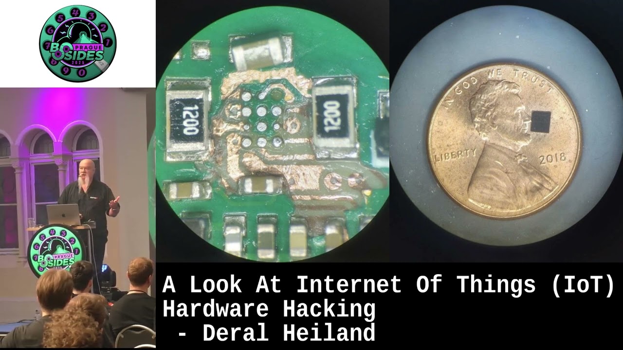
SPI, I2C, a lot of those, this works good for rewiring the circuit board to gain access to things that you want to gain access to. So, this was uh this was an interesting thing I wanted to try doing. This was a total failure to be honest with you, but I learned much from it. So, anytime you're working on IoT, don't hesitate to fail. Things are going to go bad. Smoke's going to get out. You're going to break stuff. You're going to melt things with a solder iron and screw things up. That's the only way you're going to learn. So, when you get ready to hack a device, buy more than one. Always have two. Learn from the
first one and go from there. But what we have here is a SAM module, a security access module. Uh that I don't know if you know the size of of a US penny, but it's about the same size as your one Corona I think size. It's almost identical in size. So you can see how big that SAM module is. Everything on this particular board was run in a sub layer. So the goal was how do I find out where those sub layers are? I don't have an X-ray machine. So, what I did was I removed the chip and this is me actually delayering the board down around this chip to figure out what direction the runs were going
in. And I took this down. This goes down. This is like a you had the two center layers and then you had I think six layers in between. So, basically six, seven, eight layer board. It's pretty complex board. But this is me actually cutting down through three layers. The reason why I failed is I ran out of time. This was a time slotted work that I was doing. So, uh I was not able to finish it up. But we learn a lot from this. We learn technique. We learn process. Even though I failed, I've used this method many times where I have data. I know it's running through a sub layer and I can identify by cutting down
through the layers to find out where that run is going. The bad thing is if you have like a six, seven, eight layer [Music] board, there's this old rule we used to have in the Navy Navy called 50/50 90. When given a 50/50 chance of odds, 90% of the time you're going to be wrong. So this is it. So what side do I start cutting through the board at? The top side or the bottom side? So I had a board where I wanted to get access to that run. I started cutting through the board. I discovered it starting on one side, eight layer board. I discovered it on layer seven. So basically, if I flip the board over,
it' been layer two. So I cut and I cut and I cut and I cut and eventually I was able to find it, was able to tap into it and get the data I wanted off of it. But again, you know, that 5090 rule always kind of bite you. Uh, you know, you always hope it's least in the middle so I don't have to keep going. But it was an interesting example. So what would we do if we did something like this? So my goal on the SAM module is it's a security access module. This is handling keys interchip communication access to key key data that's coming off a device or flowing between the CPU and
a SAM module or some kind of encryption module have been known to be able to capture it on the circuitry and be able to use that to decode information. So that was my ultimate goal. How do I get to the encryption module, the SAM modules, and its data? So, that's what I was trying here. Again, failed mainly because of timing. Uh, and I probably went through several boards during this process. I had a number of devices to test and do this stuff on. So, it was a interesting effort and that's what I'm trying to get you to think about it. If you're going to do hardware hacking, learn the basics. plenty of information out there for the basics,
but you're going to eventually engage things that are not the basics and you're going to go, I don't know how to do this. Experiment, try teach yourself. You can go out and ask other people. You can ask me. I can come up with a million crazy ideas you can do uh and challenge you to go out and do those. So, firmware extraction. So, this is another crazy idea I'm going to challenge you with. So uh not for the faint of heart but there is a process. So this happens to be a memory chip. This came out of a cellular module. If people know anything about these type of chips, these nan flash chips. The the first thing you're going
to think this is an embedded multimedia controller package or a multi-chip embedded multi-chip package. Turns out it is a multi-chip package, but it's not embedded. So, there's no embedded controller on there. If there was an embedded controller on there, there's devices you could buy fairly cheap where you can just drop the chip in, plug it into the USB, and it'll mount up like a hard drive automatically because it has its own onboard controller. That was not the case right here. This was an MCP. That means it contains both nan flash and RAM when it's a multi-chip package. So, my challenge was is I don't have a socket for my chip reader. Well, how do I deal with this? We've all
heard, I don't know if we've all heard the word dead bugging. It's the concept of flipping the chip over so it looks like a dead bug and soldering to it. Well, how do you solder to this? So, I have a couple items I'm going to pass around because I can show pictures, but I'm hoping this will kind of get through the audience. I only ask that you don't steal it. And if you're the last person to have it when I finish up the talk, just bring it up here and set it by the podium for me. Uh that I'd appreciate it. What I'm passing around is what we actually did. So what we do is start with we have
no socket to read it. We have no data sheet for this device. We got to h we got to get the data off of it somehow. How do we do that? no data sheet, no nothing to start with. Even though there's no data sheet on it, the pin out is industry standard. So, you just need to find another vendor's pin out. They're going to be the same. Chips need to be interchangeable because manufacturers buy the cheapest memory chip possible. So, you need to swap them out for their product. So, you you buy an IoT device, it may have one type of memory chip in it. you buy another version of it may have a different manufacturer's memory
chip in it. So you're able to do that. So the blue area up here at the top is the area that we're concerned with. That is the nan flash. That is a standard naming conventions for chips. Uh and that comes in handy later because sometimes we have to lie to the chip reader. So what we do is is we figure out where these are on the chip. Now each one of these pads is point one quarter 0.25 millimeters in size. So very solid. This has to be basically done under a microscope for the you can get a digital microscope. It'll work too for this type of thing. And then we ball it. So we put balls on it. Easy to do.
Sounds complex. When you flux these things, uh the balls stick. So you throw a few balls on there. You roll them into place. You put it on a hot plate or an IR oven and you bring it up to the right temperature. Solder melts at 183°. It's a small chips, 183 Celsius. So, it's a small chip, so you don't really have to go much above that. The chip will come up to temperature. The balls will melt onto this. And then we wire it up. Everyone's going, "Uh, what?" Okay, so the process here, and I wrote a blog on it. I recommend going out and finding my blogs are on Rapid 7's site. Because we put the balls on there beforehand, we
can take 40 gauge wire, slightly tin the end by just sticking it into a solder ball slightly, and then all you have to do is press it up against that ball and tap it with the solder iron and instantly it sets. Then you can go ahead and glue it down because uh as you see this thing going around, you'll see how small the wires are. It's easy to do. You're wondering, hey, how come these wires don't short out? This is magnet wire, 40 gauge magnet wire. It is coated with lacquer. So there's a coating of lacquer to prevent it from shorting out. So this makes this process fairly simple. Then when you get to the the
actual chip reader and you don't have a data sheet, you can always find a sales slick. Sales slicks are going to give you the highle area. It's an SLC chip. It's 2 gigabytes in size, 8bit width. You're going to get all the basic highlevel information and then you go to the same manufacturer and you look through his chipsets for those same standards. You find something that either matches your chip environment or you use that naming nomclature and wire it up to a device uh and I'll show it here in a minute. You wire it up to a device like it's a TOP 48 or standard 48 pin device chip manufacturer. So, you know, when you buy a chip that's in a certain
package, they have that same silicon in a halfozen different packages. Everything from a T-OP to various forms of BGA, uh, uh, multi-chip package, non-multi-chip packages. So, almost most of the time, you can hook it up and the chip reader will recognize the silicon on there, the serial number will work, and you can read the data off of it. If it doesn't recognize the serial number, just turn that off and let it go. I have yet to have that failed. If you matched the sales slick data to what you're telling the chip reader the structure is, it'll work. It'll work every time. You don't need the data sheets. All you need to do is know what the pin out is.
It's standardized. Hook up to it. Wire it in place. So, how do you go from there? So, uh, if you want to see this, uh, you can come up afterwards. Basically, what this is is a, uh, it has screw headers on it. So, it gives me a chance to wire all the wires where I want to. This is a dead bugger. Um, and it hooks to a socket. Goes into a socket, a standard ZIF socket on a chip reader. And you can wire any chip up to this device that you've dead bugged and it'll actually work pretty good. I'm not passing this around because this is like the only one I have and I'm too lazy to build another
one. But uh again, I encourage build build jigs. As you encounter something, need to do something weird, build your own custom jigs. Buy all the parts to do this. It makes life easier. I generate jigs for everything. I mean, we have one here. You're going to see more of them in the slides here. And I build multiples of these. It gives me a chance to be able to engage the device, pull information or connections off the device to a breakout board. Makes it easier for exchanging uh testing hardware, analysis hardware, and various things I want to do to the device. Makes it go much smoother. And this is you can see all the mini wires going to the
device. This particular device, I don't know if it's that one we're passing around. I ran into a weird problem with a device. My Pendas team were engaged with something like this and they didn't have time to do it nor did they have experience at the time. So they just dropped this in an envelope and shipped it to me overnight and I dead bugged it and it turned out the chip actually had two grounds on it. Both of them had to be hooked up. It was weirdest thing. There were actually a split ground system. Uh and that fought me for hours until I'm relooking at the pinout structure and I noticed hey what's this uh ground one ground two
thing? So I hooked both the grounds up with the jumper wires there. So we grounded everything and it worked [Music] fine. So as I mentioned earlier, sometimes interchip communication is pretty good. Uh I did a research project here a number of years ago uh where we dug in deep on interchip communication analysis between microprocessors on the board and wrote a paper on it. Over this last year, I've been focusing on cellular technology, interchip communication and cellular technology, data flowing from the main microprocessor to the cell cellular module that typically follows a couple different patterns. But so we're going to talk about how do we proper engage, interchip analysis, mechanical testing, cellular device control, manipulation, things like that. When you're in chip
interchip communication, sometimes you can do anything. You can take over the communications. You can change the communications in the flow. There's a number of different things you can actually do. So when you're talking about cellular modules, cellular module take command and data two different ways. They'll either do it over USB or they'll do it over. If they got large amounts of data to move, they're going to do this over USB. This particular camera we showed in the picture is communicating everything over USB. Most of the time the manufacturers will actually disconnect the one they're not using and leave it floating. They didn't do that in this thing. So, it kind of made it a little
nicer. It actually fully ran back to the CPU, but the CUPU just ignored the data. So, we literally cut the runs, routed it out to a board. Uh, and an extension of this, the research project we did a few years ago focused on the UR communications for interchip analysis. We wrote a proxy tool, proof of concept proxy tool. We're getting ready to ramp it up and add some more features to it called a Karen proxy. A Karen A Kh E R O N something like a Karen proxy and it is a interchip communication uh proxy. So, we can actually cut the runs serial um UART communication runs on a board, route it off to a device, and then we can hook it
up to multiple FTDIs and run our program, and it'll capture all the communications going in both directions and display it. It'll actually show us which direction it's going in. And we can actually replay it back in the circuit. We can replay our own data back in the circuit. And we can also it'll actually we can set a a a bit string change saying hey if you see these bytes this hex data string change it to this hex data tree uh and actually replay the data back and actually fuzz a device uh through interchip communications. But in this particular case uh our goal was to control the cellular module while it's functioning control it while it's in circuit. So even though
the USB is the primary command, primary data on this device, UART is always active and you can do command and data through that too at the same freaking time and have no effect. So we wanted to do something really cool. Our goal our goal on the project this year, we're expanding it out, is to completely weaponize a cellularbased IoT technology. that is instead of having to try to pull stuff off the device and to a development board to do hacks, SIM cards off things like that uh with security maybe tied in the uh EIN9 number, things like that. Avoid all that. Let's use the device. How will we use the device? So, that's what we're
working on. Uh we did a bunch of that stuff last year, published a paper on that also. And we got a um and typically this is how the how we would do it for cutting runs. So we have the receive and transmit here. And then what we do is we go further up through the runs and we we hook wires both sides of some spot and then actually cut the circuits. There's no time dependencies, timing issues with UART. Fairly slow for the most part. So you don't have any timing issues. So you can route all the communications off pretty quickly. So this is what we did on the cellular device. So we're able to tap into the
middle here. And what I'm going to show you here is a video. We wanted to do a proof of concept video. So I want you to understand what you're going to see. Modules take AT commands, okay, to control a device. So we wanted to actually turn the device into a port scanner to scan things over the internet. So, in this particular [Music] video, you get to see me monkeying around with it and pointing at stuff. Funny. What we did was we hooked up over here. What we're wanting to see from the mic from the cellular module is it to go into ready mode. Even though that the CPU doesn't care, soon as we power it
up, this thing goes into ready mode. Once we get into ready mode, we disconnect that and we connect our application. So, we're good. takes commands. Qi scan actually use socket functions at socket functions. Anything with a 0566 the connections clo open 00 means there's an open port. So we from this right here we're actually able to do port scans from within the device over the internet. We can see port 80 is open, port 8080 is closed. 9929's open 31337's open rest of them are closed. I think 22's open are closed also. So it's not fast as inmap but hey we're actually using a piece of IoT device to carry out some form of of attack and the goal is
to take it to the next level where we completely weaponize it to carry out not only port scans but also real world attacks against cloud services and stuff like that. So where it becomes uh really interesting, the device we had was using a public APN. So it was actually going to the internet for the most part, but there are a number of devices that use what's known as a private APN. And from the private APN, there's a VPN service back into internal networks. So if we have a device like that, we can actually take the cellular device, weaponize it, so we can pivot through it to actually gain access to internal company resources and use all the security
that's built into the device itself to do all the authentication for us and then we carry out our attacks. So uh running close on time, so I'm going to speed through some of this stuff. So I wanted to do root access to give you an idea of this presentation here. We actually here's another device to pass around so everyone can see this. This is the camera without the Wi-Fi attachment, but it happens to be a Wi-Fi based IoT camera. Easy enough. You can buy a million out there. This happens to run a Nenenic T23. We don't have a data sheet on this. So, when you don't have a data sheet, you have to do a little more
digging. We down here we have a eightpin uh standard SPI flash zero flash. And that's the Wi-Fi unit, which at this point I don't really care about. And but when we look at this device and we don't know anything about it, we need to find out where is zero at. Is it accessible? There's no markings on this board. You'll see it goes around. So one of the things I like to do is when they don't have any headers or anything on the board, often they don't want you to access it. And in those cases, sometimes they will not connect them or they'll leave them floating. First thing I do is I analyze the board and go, okay, how many of
these connectors are not connected to anything that I can visually see? And those are the first ones I probe. The ones at the top happen to be serial. Uh we're able to hook a a logic probe to it and we can see over here uh serial data coming off of it. So now we know that's serial. Later on though, and this comes in handy sometimes, you can go back to the manufacturer even though he won't give you a data sheet for something. Maybe there's a data sheet released on something else that is in that same series, older series, maybe a newer series. In this case, the T31 did have an actual data sheet, and it pretty
much mapped out pinwise the same as the T the T23, which is one option for trying to identify something in in a chip by using other stuff from the manufacturer. So then we went ahead and wired into it. And you'll see that that's 40 gauge wire. You can see the pins are very small. So you have to get good at soldering. I know that sucks, but you know, if you want to hack hardware, life's much easier if you learn how to solder a little bit. So uh in this particular case, we hooked up to it. We booted it up, came up running, and uh it eventually came up and we had a root log on or log on for
it. We didn't know the password. How do we get access to this device? Well, it turns out that uh there is a way to do that. So, we wanted to get the memory off the device. We pulled pin 8. If you have an SPI chip and you want to read it in memory, pull pin 8. Pin 8 is the uh power line because if you disconnect power, hook up to that. Your chip reader is going to power up the CPU nine times out of 10 and the CPU is going to fight you on the SPI communications. So, you pull the power pin, put insulation tape underneath it, and then you can go ahead and actually hook a clip to it. Hooking
clips to these things totally sucks, but once you get used to it, after a little bit, you'll be able to get it on there. And then we go ahead and we actually dump the memory. So, now we have the memory off the device. Next step is to figure out what we're doing. So, I got video for the next part. And we will try to walk through this. They keep telling me I got five minutes, but we started five minutes late. So, I'm going to steal it back. So, turns out real quick when I was in here, I brought the entire firmware up in a hex editor. Okay, you can actually use binwalk and blow it all
out, but literally it was no use to me. So, I went ahead and brought it up in uh hex editor because now I can see the Uboot and all that stuff. the other screen. I'm not going to go back to it, but if we seen the boot process, there was something weird that I never usually encounter. Typically, when a device boots up, you see the Uboot process come up. Everything load, it loads kernel, and then if they wanted to secure it, they turn console off and kernel loads. This one here apparently had console turned off with Uboot mode. There was no Uboot in there at all, and you couldn't manipulate, break into Uboot at all in
that particular case. So, it was a total pain. but it only showed kernel load and then the lo on prompt. So I went into the device. I looked for Uboot. I found it. I tried altering Uboot settings to try to get it to go into various modes. Wouldn't do it. Seemed to ignore most of the stuff I put in there. I also found the shadow file in here with the hex editor. I changed the password in there. Didn't change nothing. Didn't give me a password. Strange. Not unusual. I've seen devices that'll actually use um virtual the virtual RAM that's loaded up from kernel to overlay uh on the devices. So sometimes you get weird things like that. It may have been that
it may have been something else. But we wanted to get a little further. So it turns out there's a u right here there is a command cmdl console equals that there is a argument within the booting process. This is where commands are passed to the kernel during load process. So what we going to do is let's just alter commands loaded to the kernel and see what we can actually get. So there's a command called single. So we loaded out. Always remember, put a null bite in there or it's just going to keep reading everything until the end and crash. So we went ahead and did that. We saved it out to put single in there. Saved it out
and we're going to copy it over. Now this is where it becomes a pain in the butt because we're going to we're going to move the chip back and forth. Move the software back and forth a couple times to get to where we need to go. But in this case, we're going to go ahead and this is my chip reader. Can't really read it see it very good, but generally I'm loading what I just altered back onto the chip. And then we're going to go ahead and transfer it to the actual device again. Uh and the uh the one I'm passing around the the chip still in circuit. The one that I did here, I
tried something different. I actually put a socket where the RAM chip was and put a socket in there. So you'll see me taking it in and out while I'm doing this. You don't need to do that. You can lift pin eight and do it with a chip, a a clip. So we burn everything onto the [Music] chip. Now we put that in there. So we're going to have a single command that's passed during the bootload for arguments passed to the kernel. And you can see the white socket up there um right there. And there's a bail that closes on it. And I have to put the Wi-Fi header back on it or it does weird
things. Uh, and now we're going to go ahead and uh reboot the device. This is very low visibility. I apologize for that. But as soon as we see this uh we're instantly in there is uh no lo on prompt anymore. It doesn't boot up. We're in single user mode. The thing though when you're in single user mode that needs to be considered is let's see where we're at. That's a little more visual. So in single user mode you have to do a number of things. First thing I'm doing here is I'm looking at the run control on the device because I have access to that. So I can see some of the run control stuff. So we see what needs
to be loaded to bring the thing up into full operational mode. But some of the first things we need to do is we have to load proc and cisfs. Proc and cisfs are part of the kernel. They have to be loaded up so the kernel can interact with the kernel data. So the device can interact with kernel data. So we loaded that up. Both of those proc and cisfs. This is the process to bring out a single user mode to some point. And now we can see proc data is in there. And that way we can inter interact with objects on the device. Now that we have that, we looked and we're actually now be able to load kernel driver. INS mode
is a kernel driver command. This is a custom setting on this device. This driver setting that's being loaded right here will give us ability to read and write flash memory. So now we can start mounting up off the flash menu. We mounted up a squash FS. We mounted up a GIFs 2 file system uh block five. Now we have access to the whole system. The only thing we haven't loaded is kernel drivers for network communications. I'm really not looking for that right now, but you literally you can load all the kernel drivers and bring it out of single user mode and remain root. So we go to the shadow file in the config directory and we literally rewrote
it. So we rewrote it. So shadow has a blank password on it now. But uh now we have to get single out of there because it's in our way. So, this thing's going to we're going to go ahead and swap it back. We're going to bring it up again, take the single out of there, put it back. The goal is is we'll load it back on the device and now we can boot up and it'll prompt us for a password and we'll be able to log in with root with no password on the device and then that becomes permanent. Then you can use further testing from there. If you stay in single user mode and bring it out of single user mode,
most of these devices have weird watchd dogs on them and if it doesn't seem interaction after a short period of time that it expects is normal by the kernel, it'll reboot. So if you stay in single user mode and bring it out, it's going to eventually reboot itself if you stare at the screen for more than a few minutes. Uh and you don't want to do that. So the best thing is get full blown root access with a root password and that'll remove a lot of that because then the device will be in full operational mode and you can begin interacting with it without any problems here. So yeah, this is kind of the boring part of me like cut
paste burning the [Music] firmware. I like already the picture already ran. Um now we're going to copy it over there. We burned it. I had multiple VMs that I was doing this on. I don't want to explain why I have to do that. It's a workrelated thing. Um, but uh, so we're going to go ahead and copy the image where we took single off, put it back over there, burn it to the device. I may actually get close to my time now. I miss it by a few minutes. They can fire me. Oh, we got we're still at this part here. Oh, sorry. Single. H. Okay, so now we need to remember single. We got to
get single out there. Put quiet back again. Null bite, null bite. Make sure you put the null bite at any any changes you do within the hex editor or it'll just keep loading crap until it craps all over itself. Uh, and that's not what you want. So, we save that out. I use standard hex editor. I assure you there's way much better professional hex editor programs out there. I just got so used to using this for so many years, I could just move right through it fairly quick. Uh, also, uh, I don't type this quick or hack this quick. This is like double time speed. If you're wondering, going, "My gosh, this guy freaking types
quick." Uh, but then I'm like typing slow there. Could you imagine how slow it was when it wasn't running two times the speed? Yeah. The last thing you want to do is lean over my shoulder when I'm hacking. It's like, man, you spelled root wrong like four times. And I cut most of the garbage out of here of me doing
that. So now we're burning it. So it burns the reader's going to burn it out. When you're burning to a chip, the reader's going to burn it. Then it's going to validate it, make sure it's all correct and no errors. Uh there's a number of good readers out of there. This is a uh a T-56 T-56 reader. It's a pretty good reader. And you can see the socket up there at the top, the white socket. Uh, I just put a socket on the board to try to play with it because I was trying to find with a an operation would work well at Defcon. This would not work well trying to run 200 people through this
exercise. They'd break every one of my devices cuz this thing was just a total nightmare. Okay, so we put it on there. Now, we're going to go ahead. We're going to reboot the device. Why does it change screen color? This is terrible. I I apologize for that. Root, no password. Now we're root on the device. So now we have full route on the device. And there's a tons of cool things you can do once you root on the device. You have access to everything that device has access to for the most part. Uh some cool hacks we found over the years where you can do some crazy things. We did this on a device one time where eventually found
out based on the applications they were running. We went and got the application manuals, went through the application manuals of the command application they were running on the device because it was a a paid product, but manuals were free. And uh we actually found out way to actually send commands back to their core system where we could actually impact every device in the world. So there's like really crazy security issues uh implied in this. So let's uh jump over here real quick. Let me go ahead and play from current slide. I just want to show this screen real quick. This is if you can get this, this is a list of my blogs, papers that
I've written, stuff like that. I'm also on LinkedIn and I publish a lot of the stuff and links for uh papers that I'm creating out there for that. Um don't think I have time. I went over five minutes and they're looking at me bad. So um I'll be around the rest of the day. Catch me. I may be outside. who knows what sitting out there. Uh if you want to talk about this stuff, but please do. I love talking about this stuff. It's fun. I hope you guys enjoyed this. [Applause]
Related talks
 23:23
23:23 50:55
50:55 39:20
39:20 35:12
35:12 30:48
30:48 46:54
46:54