Introducing Serberus: A Multi-Port Hardware Hacking Tool
Show original YouTube description
Show transcript [en]
so any hardware hackers out there just a couple well this this tool is intended to make it easier to get into that so hopefully we'll end up at the end of this talk with a few more uh if you have any questions raise your hand feel free to interrupt uh I'd be happy you do it this is a pretty informal talk um it's it's geared around more about demonstrating the tool than uh talking about it but I am going to talk about the process of of building it just so you can uh see that uh you know maybe it'll inspire you to try and uh build something on your own before I did this I only had a moderate knowledge of
of how to use Eda tools like kead specifically and by the end of it uh I felt like I really knew what I was doing so it's a great way to get into that so who am I uh I'm a principal cult uh principal consultant at mandiant a pentester uh I do a lot of embedded systems testing but also a lot of other generic uh you know Network external web app that sort of testing U mobile application things like that but my my specialty my passion is embedded systems uh and I'm professionally known for actually breaking those systems that I'm working on that's that's uh what I did and probably the biggest the first one I
did was uh about 10 years ago uh I had a BMW don't judge I I like the way it drove uh and I wanted to have an iPod interface in it and I thought it'd be easy I thought it just a little USB connector that'll run to the back of the head un in it it turns out it was a lot more complicated than I thought but I decided to tackle it anyway uh you can see in the middle picture here it has uh some Fiber Optic Cables the orange cable is the one that I had to add and splice into a fiber optic Loop uh that's called the most Loop if for those Automotive
people out there that's a basically it's a multimedia Loop designed to pass audio data and I actually had to recode everything it turns out the USB interface actually routed itself back to a telematics unit in the trunk and then that spliced into the most Loop and then that most Loop uh moved up to the head unit but I figured it out um and as I was recoding the car to tell it that it actually had that interface I forgot to hook up a battery maintainer and bricked the car uh so what I had to do is I actually had to boot it back up and finally I figured out what it was it was in transport mode uh which is what they
do to uh preserve B life when it's on a roll on rolloff ship moving across the ocean uh once I figured out how to do that and get it back and after adding a few gray hairs to my inventory uh I got it back and and now I had iPod um and I felt like oh wow I I'd actually bricked it and brought it back uh now for a more expensive brick this was a few years ago this was during the pandemic uh I had one of these it's a Tesla Model S and I decided I wanted to make it faster uh when I when the the car was sold uh I was the second owner it didn't
have ludicrous mode it just had what was called insane mode and I had to get that extra half second of 0 to 60 time so I decided I wanted to figure out how Tesla did that in the service centers uh so I figured it out I had a test bench which I I'm actually going to show JTAG connectivity on um worked through the process and figured out how to add ludicrous mode to it I had to drop the battery pack replace the contactors replace the fuse and reflash the BMS with different code uh during the the ref the reflash process putting the battery back in the car all works fine uh it accepted it accept the new
battery ID but the cars have this thing called the security Gateway and the security Gateway actually stores the configuration of the car what battery pack you have you know what air conditioning model revision you have uh the drive units every component on the car from all the way up to the door handles have their own little code that goes into this configuration and uh me in my vanity I wanted the little icon for biohazard mode even though I didn't have the proper climate control units for it I just wanted that little biohazard symbol on my uh AC when I clicked on it and because my car didn't have the hardware for that during the process of recoding the battery and
everything else it died uh and it wouldn't take the the reflash it wouldn't allow me to re-engage the contactors the parking brake was locked and I had to get it towed home across state lines and during the process of uh basically being miserable and commiserating with the about the big mistake I did I figured out the problem was by looking at the log files that I generated and figured it out that it was that that one little configuration line that I added removed that uh reflashed the car it came back alive and and now I have ludicrous mode so that was my second very expensive brick but it taught me an awful lot about the car
configuration and uh UDS car hacking in general it was a fun process uh I also did some avionics hacking uh with some help of a gentleman in the audience who's waving right now he was a a big help it it took two and a half years from findings to release and it was a a pretty momentous occasion but I feel like we actually made some really strong positive change in the industry now uh there's an actually an Aeros Space Village now that where they they freely discuss these type of things and uh I kind of had the a release on the kind of the first year of that Aerospace Village and and felt like we really
moved uh moved the needle and actually allowing security researchers out there to do this type of research um in a positive way doing it right working with industry uh you know doing responsible disclosure all the rest of it so uh why do we need another USB to serial device we have the time up we have the tiger we have all these little little units like this units like this that you can come up and see if you want um I had some particular use cases that I needed it for that uh I didn't want to have a big spaghetti mess of like 5 USB cabl sticking out of my device so I decided to create my own um so I I had
was trying to basically connect to serial devices on both ends and for that you actually need two uart connectors because you have to have deal with the send and receive and then be able to join those connections in the middle um I had a tiger that had level shifters cuz I was dealing with something that was working at 1.8 volts um and I had my little four port uh modules so I decided to basically combine them together and I came up with the name cus and honestly the name took me longer than the design I went through so many other iterations before I stumbled across this one so it's like a combination of Serial bus
and curus the the multi-headed dog and do you like my AI generated image that I created for this um or that some AI created for me that I took uh so combine the two so this device that I created and here's the the first real prototype of it uh has three yart connectors and then multi one multifunction JTAG uh s swd uh 10 minutes in or 10 minutes left okay I want to make sure I understood the signs thank you uh um so uh you know SPI i2c connectors uh a level shifter that you could absorb connections you could basically connect to devices that worked at a logic level of 1.6 all the way to 5.5 it's the lower levels where
you run into problems if you're dealing with a really low power iot device or home device and you just try and use a regular uh USB to uart device it it may not um the the ones or the the positive signals may not rise up enough to trigger and and be identified as they are so that's why you need the level shifters uh another some other things that I wanted to change I want to simplify the connectors I wanted to use an MSO style ribbon connector uh if anyone has ever used a mixed signal osilloscope uh you know they have like the little 20 pin ID connector that breaks out into uh 20 separate pins that
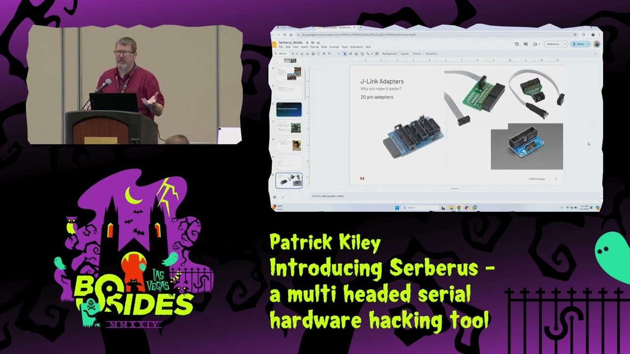
you use to connect to your logic device I want to have that simple connector on it and then also the um the Sear which is a very common and and kind of professional level JTAG debugger device has that same style of connector uh I also wanted the ease of connecting up a logic analyzer uh for those of you who do Hardware hacking you know how much you use a logic analyzer um having it directly on the line without having to have multiple connections on the little tiny pins that you're connect to uh little made uh my workflow a little bit easier so we added that um and then it has a a single little like cortex debug connector on it
as well uh anyone who's actually used a Seer jlink has seen one of these adapters you're moving from you know your standard 2.5 millimeter pitch device uh down to some really small connectors because your typical cortex debug connectors you can see down here and the lower right has a really fine pitch and use these really tiny ribbon cables to connect directly to the device uh the little snap-in connectors for programming devices it's the same story uh you know need to be able to connect those up and trying to have a whole bunch of DuPont wires scattered across that uh makes it a little more difficult whereas if you just have a single thing that you can plug in and do your flash
programming directly I I thought that might make it a little bit easier and it has as you'll see when I connect to this Automotive Target um and then uh I wanted indicators for each TX and RX um the the chipset on this is the ftdi 4233 uh the 4232 and the 4233 don't have enough pins to drive eight separate LEDs so what they actually do and they didn't really Define this in the earlier versions of the data sheet is they actually use the eprom connectors so on an ftdi you can program your own serial number your own VIP ID which is how the computer identifies itself and which drivers to use um that's all programmed on this
little tiny eom on the device it's it's right down here below the main chip but it only uses it during the initial startup of the device so they they repurpose the eom connectors up to the shift register and use it to drive the LED indicators I included that uh feature on this so uh now I'm going to show the UR demo this one
what yeah
we got to make a an offering to the demo Gods here that this will
work this is the first of three demos so we'll have time for plenty of the other ones
so I don't like to use putty okay let make sure I have this correctly selected com 3 so when you connect it up uh it'll actually let me uh bring that back up because it's a it's a good thing to show it'll show up as four separate uh serial USB to serial ports in your in your machine um on a Linux machine it'll be Dev TTY uh I like this particular application for what you'll see in a little bit when I do the avionics demo but you can see it showing up as Comm three four and five and six the first don't mind me but we want to make sure we catch all your words because
you're going to be back and forth of it it seems sorry for the interruption so here put this here put this on a Pock for you on the edge and then we're going to go ahead and mute that okay M give it one second was it uh a lot cutting out how's that how's the audio we're good good okay much Sor okay yeah no
problem one of question are you going to put that on the big screen or is that only down here uh that's only down here there's no way to put that up on unless you have a camera that can point it at it so that's what we're doing is going to point the camera to try to K what you're doing yeah it's it's difficult to do it from above we don't have one of those mirrors so tell us if we need to follow you or that please sounds good okay and let me move
this and you can actually see the device booting here so this is just a simple uh demonstration of the basic uart connectivity this is a Wi-Fi router that's no longer in use at at my house and uh it's a great way to get into embedded Hardware hacking that's why I wanted to show this one uh if you want to start learning about testing embedded systems uh if you have an old Wi-Fi router rip it open 99% chance you're going to have some type of pin header that looks like this on there and all you have to do is either solder on the pin header or just connect to it if you don't have it um
you can use a a little $20 Amazon logic analyzer to verify which one's the transmit pen and you'll be able to see the device boot um okay yeah that shows well enough up on the screen uh and that's just to show you know very simple connectivity I have it connected to the uh the first U uh you can actually send and receive on this but this particular device takes a really long time to boot so uh I'm going to skip this and and move back to the rest of the presentation and if you look closer you can actually see it flash uh that's one of the indicator lights that's a really good way to check and actually see if
you have have connectivity is to verify the status of those indicator lights so moving on from that uh now while that one boots and I can show the two way I'm going to talk about the uh the design process so uh first I just built a proof of concept using breadboard uh it was a really ugly unclean signal but it verified that I could get all four channels working simultaneously off of just a Dev board demo Board of the Ft 4233 that I ordered um I should also mention uh I'm not an electrical engineer I don't even pretend to be one I took a couple years in college and then got distracted by college uh I got ended up getting my
degree in economics but it still kept an interest in it uh but if you asked me to like recyc kchu equations I couldn't do that uh but what I can do is like look at a data sheet and um copy what's on it uh pretty realistically so I can hack at it which is um the where I'm kind of going with that is don't think you have to be an electrical engineer to build something like this this um you know I looked at the signals on this on on a scope uh they're all really clean I just followed the uh the guidelines for how to uh clean up a signal how to provide stable power to a device and there's
even another device I provided uh like a stable 30 volts through a voltage regulator just by following the guidelines and using the built-in Dev tools that the uh the board manufacturer had out there uh something complicated yeah you'd have to be a dou e but very simple device like this don't be intimidated by it like that if you want to try designing your own badge uh go get kecat it's free and download it install it and and just start playing around with it you can um find plenty of Open Source designs out there where you can download the schematic you can download the the Gerbers and start moving stuff around seeing how to route things and and that's really how I
figured out the process uh so this is how power Works uh as I can see it has a if you can see it has a little switch on the front um that switch is designed to select the voltage level of your target um you can see that there's a 1.8 volt voltage regulator that's the guy up here there's a 3.3 volt regulator that's the uh middle position and then for 5 volts it actually just uses the USB level which is at approximately 5 volts but it's basically close enough uh there's a little um basically it's like a Power Protection chip that's right off of the the USB connector uh that's necessary in this with this particular chip
Set uh the indicators this is the level shifter that uh has that you can see there's a just a couple caps in here to clean up the power um alternating red and green uh here's a little bit more on the level shifter so I had to add uh the other designs out there had two level shifters I had to add a third as an additional output buffer and what those do is they take the voltage level of the ftdi which is I think pretty sure it's 3.3 volts and it'll shift it up or shift it down and there's also a fourth position on the switch where you can basically select it'll actually run off of the voltage of your target if you
have something running at a really bizarre voltage like 1.6 volts 1.6 of the minimum of these level shifters um all the way up to 5.5 if your if the logic level is is Shifting that dramatically and it will adapt the signal on the ftdi side down to the 3.3 or on the on the output side it'll shift it up to the uh voltage level of your target uh so this is the the first attempt um put everything together by hand uh the 402 components were really interesting to hand slded they're about just a little bit bigger than a grain of sand uh but I have a microscope so I figured it out and um it worked but I
discovered right away that the little 20 pin uh JTAG connector because of the little ears on the end of it uh wouldn't plug into it so it was it was not compatible with the initial design so then I went in to the second version and the second version I did very quickly and I just searched JTAG pen out turns out I grab grabbed the wrong JTAG pen out I had the grounds and the signals revers so the the grounds were actually on the keyhole side instead of on the other side and so I did one more revision um also decided to you know put some additional labels in it to figure out everything the only label I really
want to add now is one that identifies uh the voltage levels so when you you know if you're moving the switch left or right if it's going up or down in voltage uh and then I ordered some prototypes via PCB way uh so I got 25 of them um to hand out to uh co-workers because I'm not allowed to hand them out to people that are not uh employees of my company just yet while we're working through the release process um and uh we're at the current revision so here's how to use it uh serial access I kind of already showed you uh you can either just use putty specify the B rate uh or use screen or whatever your your
favorite tool is this one is just a very simple serial tool on a Mac uh for for JTAG now it's getting a little bit more complicated and I'm going to show the demo of that one in just a minute um if you try and use open OCD out of the box just do you know apt install open OCD it probably will not work the package maintainers version of open OCD doesn't have all of the ftdi chips sets supported out of the box uh fortunately it's very easy to build there are very few dependencies uh you can just pull it off of gith Hub and and do a build and then when you're doing the configure you just have to enable
ftdi or or any other additional chip siips that you want to use um and here's a little example showing that it actually worked uh for uh JTAG SPI for doing flash programming if you want to jump flash ROM off of something or actually use it to program Flash FL uh flash ROM itself is a little buggy a lot for the same reason it's using a fairly recent ftdi chip but fddi python you can use to dump Flash and that works really well you just need the device Uris if you run lsusb it'll give you the uh uh PID viid P of 403 and 6041 which uh you need to specify using the uh the the python tool and it'll
show up and this is one the four uis that'll show up on your your Linux machine and now for the JTAG demo so what I have here is an automotive Target going try and connect it make sure it's in J tag mode so there's a switch up here next to the uh the level shifter selection that switches it between serial wire debug and JTAG mode um it uses the same sets of pins uh but you know where you need like the pull downs and pull-ups and everything else is a little bit different but it just to move it between those two modes it's just single uh switch connection this is going to be JTAG though one
okay okay it's showing up you can see 403 6041 and yes I know I'm running uh open ocds pseudo and that is a bad habit don't do that
and you can see right here I can see the free scale free scale chipset on this Automotive Target um this particular free scale chipset doesn't have any other definitions supplied under open OCD so I can't really do anything else exciting with it um with but with this if you were to read through the uh the JTAG descriptor for it and Define your own uh chip Define your basically your own definitions on this you could uh dump the the Gateway configuration what I'm actually connected to if we get the camera to grab that in a second to zoom in on this is I'm connected to the outside pins of this connector right here this is the JTAG connector for the the
vehicle's security Gateway um for an automotive Target a security Gateway is essentially the firewall of a car and and I have uh basically JTAG access to this JTAG I can read write I can halt it I can change the specification I can do whatever I want to um the security Gateway sits between the canvases of the vehicle and the infotainment system you know the internet connection everything else so it's it's a very juicy Target that's the one that had the uh configuration file that I had to change when I did the the ludicrous stuff that I talked about earlier and I'm going to grab this chip I dropped just so I don't forget it this
is the actual main CPU that drives the screen it's an Nvidia Tegra uh it's an interesting Target because it's the same processor that's run on the Nintendo switch uh subject to all the same vulnerabilities and luckily it it has a little hidden USB connector that gives you uboot access as well so um have fun if you want to explore that uh these uh aren't used in the current versions of the automotive of the car they came from anymore they've moved like two revisions past that went to like Intel atom and now I think they're on an AMD ryzen version of a of a CPU but the Nvidia Nvidia Tegra um has some Hardware level vulnerabilities so that that's why they
they moved off of that um the the Gateway itself though that's it's a pretty juicy Target if you ever want to start messing around with car hacking
that all right so now we get into the other uh use case for this particular device and that's multiple serial um I had intended to show examples of um the acaron proxy with this particular device uh but I I broke my Distribution on doing that and uh maybe I'll have it working by Defcon um more importantly though I will be able to actually show connecting to the the avionics and and that's really the fun stuff uh the other thing that basically the cool thing about acaron proxy it's one of the few serial man-in-the-middle tools out there so what you can do is you have an embedded device uh there's an interchip um Communications that might
occur over cial really common for things like cellular modems I did I just drop out okay uh really common for things like cellular modems you'll see it like run at commands just over the serial bus uh and if you can get in the middle of that uh you can do some interesting things uh so one of the use cases of this is is to actually find the serial bus make some small cuts on the board and then connect one Ur to each end and then use software to join those two and then occasionally modify uh data on the Fly and with the actor on proy can actually do that uh here's an example of it actually
setting it up on this one uh watching data past uh this is actually from from their site uh I had it working for a little bit but then I I broke some stuff uh and then this is uh pretty much the use case that I wanted to show before I was told not to um this is transponder Communications now this particular avionic set does not have a transponder um that's by Design um but if you look at the communication on this screen you can see something right away you'll notice that the messages always begin with one zero and then it's two or C but if you if you look at where the bits line up it it's a
pretty easy mask to identify and it always ends in 13 so using that it's pretty easy to actually look for that sequence of btes and and break on it and realize that you actually have you know know the message incrementing um and I'm going to show that on the avionics here in just a second so now we got the uh the fun part the avionic demo this is going to take me just a minute to plug in
thankfully there's really good Lighting in here and I can see what I'm doing
success okay um did this presentation earlier at uh at black hat and anytime I tried to connect up two units at the same time um it would lock everything up I think there's it's probably because there's some different grounds going on doesn't make sense entirely but I'm not going to take that chance I'm just going to show on this one and show how there's another one just just right here next to it just CU it's it's the demo gods and they're being kind right now so I don't want to uh tempt F so you can see I'm using uh this tool H term and and right now it looks like garbage because it's all in actual hex so we
don't want to see asky now I happen to know that it's a 21 by message now if you hook up a logic analyzer it's not
working
oh okay I'm actually hooked up to the other unit on this okay
okay I'm going to
reset I spoke too soon about the the demo Gods oh I know what the problem is have to set the right B rate oh there we go yay all right so you can see that I've got the same beginning and end of the messages here and they are all in HEX uh all the messages from this particular device now this one has a completely open design um The Source material so basically the the the software interface specification if you will uh for this particular avionic set is is completely open they tell you how to build devices that interface with it so they'll basically tell you that uh the start of message is an 82 and uh the
end is an 83 in HEX now you'll notice are we zoomed in on the uh Mr camera person are resumed in on the avionics okay uh you'll notice can you see the data shifting I can't really see it from this angle and then this is the uh attitude heading reference system basically that's the electronic gyro of the avionics it's basically telling it where it's relation to is is into the ground and how quickly it's changing now it gets its truth also from the compass which I have a connector to but uh maybe right here at the end we'll try and connect to that and see if we both at the same time um but uh the the
main method of communication on this device is actually canbus or because they want to be interoperable they also offer cereal so um I've connected up to the cereal so we could do additional instrumentation work and uh exploration of it uh but it also it'll connect up to a transponder connect up to a radio um adsb in so it'll actually see the aircraft around it and just put them up on the display here but you can see everything shifting as as the gyro on this particular device moves so now that I've shown that any questions before we uh try and temp fate and see if I can get another connection on this all right good let's let's try
it
wait for
hey look at that
sort of working
ask you can see it's a little unstable of a connection here now it's this is just connected up to the compass now the compass has one position basically it doesn't care about attitude it just basically cares about direction of travel in relation to Magnetic North I'm going to disconnect the other one just in case that's what's causing the issues and it's not maybe I just have a bad serial converter here
so this one yeah well it's acting up a little bit now um we need to get get in and actually troubleshoot that one uh you can see it's it's coming in but it's a little bursty and it's a little bit unstable uh but it works we can actually connect to multiple ones at the same time now does anyone know why I actually have to use these converters uh what's the difference between art and
rs232 you want to come up to the microphone
were you in the cell class huh were you in the cell class the cellular implementation class at blackette yes I was okay go ahead okay so um you are it usually refers to like uh that's the logic level signal that'll be like the 0 to 3.3 Volt or the 0 to 5 Volt or whatever whatever uh Supply voltage is used by the uh the digital logic your microcontroller and all that rs23 through is an older standard and what they do is they take the uart signal in and then they drive it it's a single-ended but they'll drive it either to like plus 12 or minus 12 volts I mean I think it can be anywhere in the range
of minus three to plus three to plus 20 something a minus 20 so what ends up happening is like if you if you have like a logic high from like a UR TX the the rs232 line transceiver will translate that into like a negative voltage like a negative 12 volts and when you go zero it'll do the opposite so it's sort of like inversion and boy I just gave my H away didn't I yeah that that's actually great way to describe it so really what that means is if you're looking at a board and it looks like rs232 but you're not quite able to decode it try inverting the signal sorry if if you're looking at a signal it
looks like it's a art signal um try inverting it it might just be straight up rs232 uh because it's an inverted signal uh zeros will appear as ones and ones will appear as zero and a lot of the logic analyzers won't go negative so you'll just be seeing the positive swings on it but it'll look like a Serial signal but it's it's just a little bit different okay uh so at that point I've concluded where I am at uh the the device itself is all the designs are on uh Google's site here Google serverus um I don't quite know how I'm going to sell it yet although I know they allow it I just have to work myself through the
process however that doesn't mean you can't get one um all the key cab files all the Gerbers uh the bill of materials everything that you need to build your own is out there and it's going to stay that way um they they patented the device but they patented it for intention of releasing as an open source so really they just don't want you TR trying to copy it and sell it it's Al although when I get it out there I intend it to basically be as at my cost of creation so embedded testers can actually use the device um I just have to figure out how to do it in a way that's not going to get me in trouble
with uh with the the great um people that decide whether what's acceptable at at at my company and thank you [Applause]
Related talks
 9:40:42
 24:15
24:15 40:32
40:32 1:10:35
 40:30
40:30 42:03
42:03